

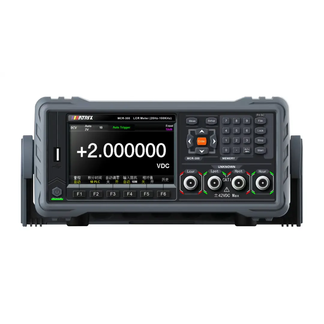
MATRIX MCR-300 Series Digital LCR Meter
· 4.3‑inch TFT bilingual display, 4‑terminal pair high‑precision measurement
· Wide frequency range 20Hz‑100/200/300kHz, min 0.01Hz resolution
· Built‑in comparator & 9‑bin sorting, List sweep up to 201 test points
· Open‑short‑load correction; 30Ω /100Ω selectable output impedance
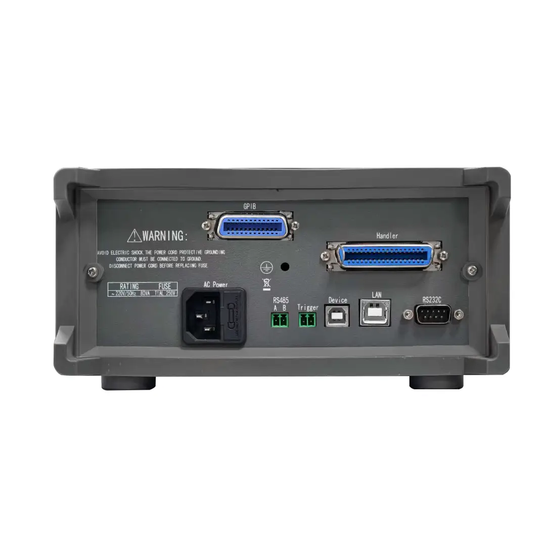
· RS232 / LAN / USB / optional GPIB & Handler interface for ATE integration
Product Introduction
MATRIX MCR‑300 series are compact benchtop digital LCR meters, covering MCR‑301 (100kHz), MCR‑302 (200kHz), MCR‑303 (300kHz) models. It supports comprehensive impedance parameters: L, C, R, |Z|, |Y|, D, Q, X, B, θ, DCR DC resistance measurement.
Equipped with a 4.3‑inch 480×272 TFT color screen with Chinese‑English bilingual UI. Adopts 4‑terminal‑pair measurement technology to eliminate fixture and lead‑wire errors. Supports open, short and load correction to suppress stray impedance influence. Test signal level 10 mV‑2 Vrms, selectable 30Ω /100Ω source output impedance, ALC auto‑level‑control function available.
Integrated comparator function supports up to 9‑bin component sorting plus auxiliary bin; List‑sweep function runs max 201‑point frequency / level / DC‑bias sweep test. Multiple trigger modes: internal, manual, external, bus trigger. Save/recall measurement setup files locally or via USB flash‑disk. Standard RS232, LAN, USB interfaces, optional GPIB and Handler port for production‑line automatic sorting and PC‑based automated test systems. Three‑speed measurement: FAST / MED / SLOW to balance test speed and stability.
| Model | MCR-301 | MCR-302 | MCR-303 | |
| Display | 4.3-inch 480×272 24 bit color TFT display | |||
| Test frequency | 20Hz-100kHz | 20Hz-200kHz | 20Hz-300kHz | |
| Accuracy | LCRZ 0.05%, DCR 0.1% | |||
| Test speed | Fast: about 12.5ms; Medium speed: 83ms; Slow speed: 167ms | |||
| AC signal level | Signal voltage range | 10mVrms-2Vrms | ||
| Voltage resolution | 10mV | |||
| Signal current range | 100uArms-20mArms | |||
| Current resolution | 100uA | |||
| DC signal level | 1V | 5mV-2V | 5mV-2V | |
| Signal source impedance | 30Ω / 100Ω | |||
| DC bias | —– | 0V-±5V / 0mV-±50mA | ||
| Test parameters | L、C、R、|Z|、D、Q、|Y|、G、X、θd、θr、RDC、Vm、Im、△% | |||
| Display range | |Z|,R,X: 0.00001Ω – 99.9999MΩ | |||
| |Y|, G, B: 0.00001μS – 99.9999S | ||||
| C: 0.00001pF – 9.99999F | ||||
| L: 0.00001μH – 99.9999kH | ||||
| D: 0.00001 – 9.99999 | ||||
| Q: 0.00001 – 99999.9 | ||||
| θ(DEG): -179.999° – 179.999° | ||||
| θ(RAD): -3.14159 – 3.14159 | ||||
| △%: -999.999% – 999.999% DCR: 0.00001Ω – 99.9999MΩ |
||||
| Zero clearing | Open circuit and short circuit load calibration | |||
| List scanning | 201 points, scanning parameters: test frequency, AC voltage, AC current, DC BIAS voltage, DC BIAS current | |||
| Equivalent method | Series and parallel | |||
| Range method | Auto hold | |||
| Trigger method | Internal manual external bus | |||
| Mathematical operations | Direct reading △ABS △% | |||
| Comparator | 10 levels of sorting, BIN1-BIN9、NG、AUX, File counting function, PASS and FAIL displayed on the front panel | |||
| Memory | Internal: 40 sets of instruments with built-in test setup files, USB storage: setup files, GIF images, CSV data files | |||
| Interface | USB HOST, USB DEVICE RS232C, RS485 (optional), GPIB (optional) Handler LAN | |||
| Shelf volume (mm) | 215(W)×88(H)×335(D) | |||
| External volume (mm) | 235(W)×105(H)×360(D) | |||
| Net weight | 3.6Kg | |||
Typical Applications
- Passive‑component incoming inspection & sorting: capacitor, inductor, resistor, transformer, magnetic‑core components
- Electronic R&D lab: impedance characterization, DCR, D/Q factor evaluation for passive devices
- Power‑supply & circuit‑module verification: MLCC, power inductor, high‑frequency component performance test
- Production‑line ATE integration: automated bin‑sorting, multi‑point sweep‑measurement for mass QC
- University & technical‑training laboratories for impedance‑related teaching experiments
FAQ
Q1: What correction should I perform before accurate measurement? A: Run open‑circuit and short‑circuit correction first. For higher precision at specific frequency, execute point‑frequency load correction to eliminate stray impedance errors from test fixtures and cables.
Q2: How does the 9‑bin comparator sorting work? A: You can configure tolerance‑mode or sequential‑mode limits. DUT will be classified into BIN1‑BIN9, OUT‑bin or auxiliary AUX bin. With optional Handler hardware, physical sorting signals are output to production fixtures.
Q3: What does List sweep function do? A: It supports up to 201 test points for frequency, test‑level or DC‑bias sweeping. Two modes: SEQ (run all points in one trigger) and STEP (one point per trigger) with pass/fail judgment for each point.
Q4: Cannot communicate with PC, how to troubleshoot? A: Verify selected bus mode (RS232 / LAN / USBTMC / GPIB), match baud‑rate, address and terminator settings. Check physical cable connection; turn off Talk‑Only mode if remote control is required.
Q5: What measurement trigger modes are supported? A: INT (continuous auto‑measure), MAN (front‑panel trigger key), EXT (Handler external pulse), BUS (remote‑command trigger).
Q6: What files can I save to USB flash drive? A: *.STA setup files, sweep‑parameter files and CSV test‑log data for offline data analysis on PC.