

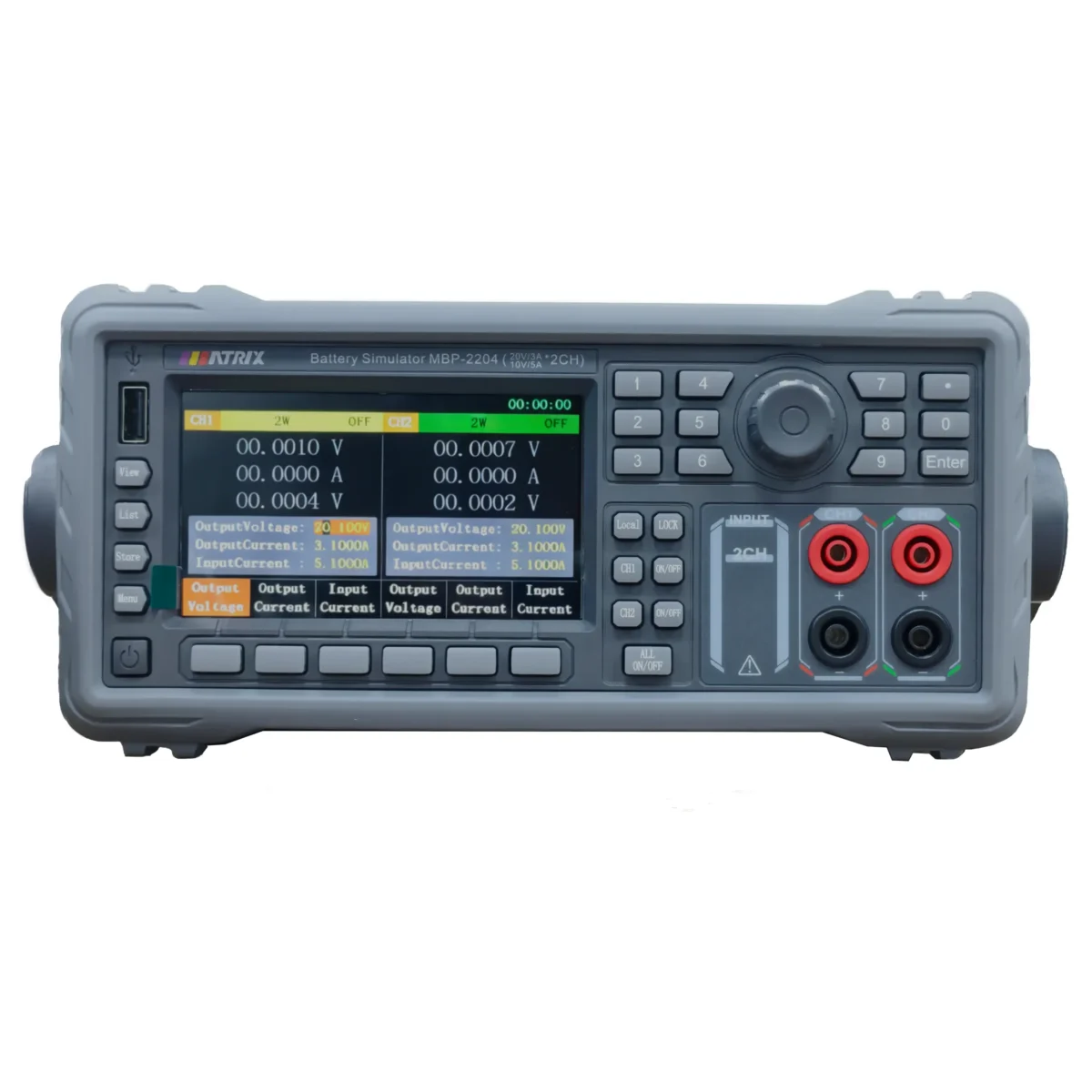
MATRIX MBP‑2200 Series Dual‑Channel Programmable Battery Simulator
· Dual independent bidirectional channels for battery simulation
· 4.3‑inch bilingual TFT display, knob & keypad dual‑control
· 0.1 mV / 0.1 mA high resolution, rise time ≤2 ms
· OVP/OCP/OTP protection, 2/4‑wire sense, ±30V DVM
· List sequence & waveform view; RS232/LAN, SCPI/MODBUS
Product Introduction
MATRIX MBP‑2200 series is a dual‑channel high‑precision programmable battery simulator, covering MBP‑2201, MBP‑2202, MBP‑2203, MBP‑2204. Two fully‑independent output channels support bidirectional current for simulating real‑world battery charge‑discharge characteristics, ideal for laboratory R&D and production‑line automated testing.
Equipped with a 4.3‑inch high‑visibility TFT color screen with Chinese‑English bilingual UI. Operate via numeric keypad or multifunctional rotary knob for quick parameter configuration. Featuring ultra‑fast voltage rise time ≤2 ms, low ripple & low noise, intelligent fan cooling balancing noise reduction and heat dissipation.
Each channel supports independent setting for voltage, current, battery internal resistance and fault modes (open‑circuit, short‑circuit, reverse‑polarity). It integrates DVM voltmeter, 2‑wire /4‑wire remote voltage compensation, List sequence programming, real‑time waveform view, local / USB‑disk parameter storage and shortcut recall. Standard RS232 and LAN communication interfaces support SCPI and MODBUS protocols for PC remote control and ATE test‑platform building. Comprehensive OVP, OCP, OTP protection safeguards instrument and device‑under‑test (DUT).
|
Model |
MBP-2201 | MBP-2202 | MBP-2203 |
MBP-2204 |
|
| Current | -1A ~ 1A | -2A ~ 2A | -3A ~ 3A | -3A~3A/-5A~5A | |
| Voltage | 6 V | 20V / 10V | |||
| Power | 6 W | 12 W | 18 W | 60W | |
| Number of channels | 2 | 2 | 2 | 2 | |
| Constant Voltage Mode | |||||
| Range | 0 ~ 6 V | 0 ~ 20 V | |||
| Set resolution | 0.1 mV | ||||
| Set precision | ≤0.01%+2mV | ||||
| Readback resolution | ≤0.1mV | ||||
| Readback accuracy | ≤0.01%+2mV | ||||
| Current measurement | |||||
| Range | -1A ~ 1A | -2A ~ 2A | -3A ~ 3A | -3A ~ 3A/-5A ~ 5A | |
| Set Resolution | 0.1 mA | ||||
| Set Precision | ≤2 mA | ||||
| Range | -50 mA ~ 50 mA | ||||
| Readback Resolution | 0.1μA | ||||
| Readback Precision | ≤5μA | ≤10μA | |||
| DVM function | |||||
| Measure voltage range | -30V ~ 30V | ||||
| Measurement resolution | 0.1 mV | ||||
| Measurement accuracy | ≤±0.01%F.S+2 mV | ||||
| Other parameters | |||||
| Rise time at full load | ≤1ms | ≤1ms | ≤1 ms | ≤2 ms | |
| Drop time at full load | ≤2 ms | ≤2 ms | ≤2 ms | ≤2 ms | |
| Ripple | Vpp | ≤25 mV | ≤25 mV | ≤25 mV | ≤28 mV |
| rms | ≤3 mV | ≤3 mV | ≤3 mV | ≤5 mV | |
| Transient response | ≤1.5 ms | ≤1.5 ms | ≤2 ms | ≤5.5 ms | |
| Internal resistance | 2000mΩ | ||||
| Compensation voltage | 1 V | ||||
| Power consumption | No-load | 15 W | 15 W | 15 W | 17W |
| Fully loaded | 80. W | 80 W | 90 W | 190 W | |
| Temperature | Operation | 0 to 40℃ ≤ 80% R.H. | |||
| Store | -17 to 70℃ ≤ 80% R.H. | ||||
| size | mm W*H*D | 260*123*430 | |||
| Net weight | kg | 4.4 | 4.4 | 4.4 | 4.6 |
| Packing size | mm W*H*D | 330*220*530 | |||
| Packing weight | kg | 5.9 | 5.9 | 5.9 | 6.1 |
| communication interface | Standard:RS-232、LAN | ||||
| Factory accessories | User manual * 1, Product factory report * 1, Test line * 1/ 2, Communication cable * 1, Power cable * 1 | ||||
Typical Applications
- BMS development & validation: Simulate battery voltage, internal‑resistance and multiple fault conditions for BMS charge‑discharge logic verification
- Dual‑channel consumer‑product testing: Bluetooth earbuds, smart wearables, portable IoT devices, multi‑cell battery‑powered gadgets
- Power component evaluation: Small‑size DC‑DC converters, charging IC and board‑level power circuit performance test
- Lab research & education: Dual‑channel power simulation for university and enterprise R&D laboratories
- Automated test station integration: Work with host PC to run multi‑step sequence test for manufacturing production lines
FAQ
Q1: Can CH1 and CH2 run List sequence independently? A: Yes. Each channel can execute List sequence separately or run simultaneously with different voltage/current/time parameters.
Q2: How to switch between local and remote control mode? A: Instrument boots into local‑control mode by default. When controlled by PC communication, front‑panel keys get locked. Press the Local key to return to manual panel control.
Q3: How to set up 4‑wire (4W) remote sense compensation? A: Use original test cables: connect the connector with white rubber ring to OUT terminal, and the other connector to SENSE sampling terminal. Screen status “4W” means 4‑wire compensation enabled; “2W” means disabled.
Q4: Instrument output is ON but no voltage or current output? A: Confirm both channel‑specific output key and master output switch are activated. Ensure voltage and current setpoints are non‑zero. Check whether OVP / OCP protection has triggered. Verify secure wiring connections.
Q5: What is DVM measurement range? A: Built‑in DVM supports DC voltage measurement from ‑30 V to +30 V. Strictly observe polarity; reversed wiring may damage hardware.
Q6: What file formats can I save to USB flash drive? A: Supports MSF general‑parameter files, MTF List‑sequence files, CSV test log files. Waveform recording data can also be exported to USB storage.
Q7: What communication protocols are supported? A: Supports SCPI and MODBUS. Communication interfaces include RS232 and LAN. Match baud rate, address and terminator on both instrument and PC for stable connection.